- A+
I2S总线规范
I2S(Inter-IC Sound Bus)是飞利浦公司为数字音频设备之间的音频数据传输而制定的一种总线标准。在飞利浦公司的I2S标准中,既规定了硬件接口规范,也规定了数字音频数据的格式。I2S有3个主要信号:
1、串行时钟SCLK,也叫位时钟BCLK,即对应数字音频的每一位数据,SCLK有1个脉冲。SCLK的频率=2×采样频率×采样位数。
2、帧时钟LRCK,用于切换左右声道的数据。LRCK为“0”表示正在传输的是左声道的数据,为“1”则表示正在传输的是右声道的数据。LRCK的频率等于采样频率。
3、串行数据SDATA,就是用二进制补码表示的音频数据。
有时为了使系统间能够更好地同步,还需要另外传输一个信号MCLK,称为主时钟,也叫系统时钟(Sys Clock),是采样频率的256倍或384倍。
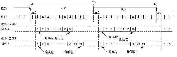
I2S格式的信号无论有多少位有效数据,数据的最高位总是出现在LRCK变化(也就是一帧开始)后的第2个SCLK脉冲处,见下面I2S格式图。这就使得接收端与发送端的有效位数可以不同。如果接收端能处理的有效位数少于发送端,可以放弃数据帧中多余的低位数据;如果接收端能处理的有效位数多于发送端,可以自行补足剩余的位。这种同步机制使得数字音频设备的互连更加方便,而且不会造成数据错位。
随着技术的发展,在统一的 I2S接口下,出现了多种不同的数据格式。根据SDATA数据相对于LRCK和SCLK的位置不同,分为左对齐(较少使用)、I2S格式(即飞利浦规定的格式)和右对齐(也叫日本格式、普通格式)。
非I2S格式如图:
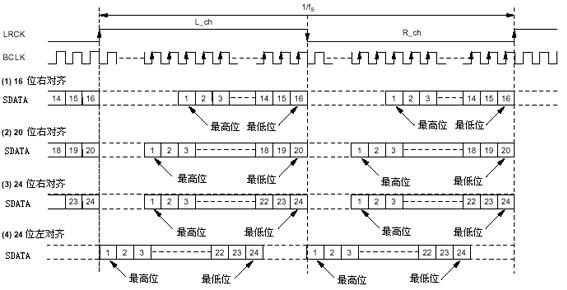
I2S格式如图:
对非I2S格式而言,为了保证数字音频信号的正确传输,发送端和接收端应该采用相同的数据格式和长度。对I2S格式来说数据长度可以不同。而且帧时钟LRCK高低电平对应左右声道的意义也不同?
注意I2S总线和I2S格式的区别,I2S总线是一种总线标准,I2S格式是飞利浦制定的数据格式。在统一的I2S总线接口下,出现了左对齐和右对齐等非I2S格式。
在我们系统Android中,设置sample_rate=44.1Khz,sample_length=16,channel=2;那么BCLK应该为2×44.1Khz×16=32xsample_rate,而实际上MCLK=11.289Mhz,BCLK=MCLK/4,sample_rate=LRCK=BLK/64=44.1Khz,BCLK和理论计算的值不符。引用“如果接收端能处理的有效位数少于发送端,可以放弃数据帧中多余的低位数据;如果接收端能处理的有效位数多于发送端,可以自行补足剩余的位”,因此这是可以解释的。
I2S/PCM时序对比
PCM
I2S
DAI概述
增加AC97、I2S、PCM三种接口说明,摘自内核文档DAI.txt:
- ASoC currently supports the three main Digital Audio Interfaces (DAI) found on
- SoC controllers and portable audio CODECs today, namely AC97, I2S and PCM.
- AC97
- ====
- AC97 is a five wire interface commonly found on many PC sound cards. It is
- now also popular in many portable devices. This DAI has a reset line and time
- multiplexes its data on its SDATA_OUT (playback) and SDATA_IN (capture) lines.
- The bit clock (BCLK) is always driven by the CODEC (usually 12.288MHz) and the
- frame (FRAME) (usually 48kHz) is always driven by the controller. Each AC97
- frame is 21uS long and is divided into 13 time slots.
- The AC97 specification can be found at :-
- http://www.intel.com/design/chipsets/audio/ac97_r23.pdf
- I2S
- ===
- I2S is a common 4 wire DAI used in HiFi, STB and portable devices. The Tx and
- Rx lines are used for audio transmission, whilst the bit clock (BCLK) and
- left/right clock (LRC) synchronise the link. I2S is flexible in that either the
- controller or CODEC can drive (master) the BCLK and LRC clock lines. Bit clock
- usually varies depending on the sample rate and the master system clock
- (SYSCLK). LRCLK is the same as the sample rate. A few devices support separate
- ADC and DAC LRCLKs, this allows for simultaneous capture and playback at
- different sample rates.
- I2S has several different operating modes:-
- o I2S - MSB is transmitted on the falling edge of the first BCLK after LRC
- transition.
- o Left Justified - MSB is transmitted on transition of LRC.
- o Right Justified - MSB is transmitted sample size BCLKs before LRC
- transition.
- PCM
- ===
- PCM is another 4 wire interface, very similar to I2S, which can support a more
- flexible protocol. It has bit clock (BCLK) and sync (SYNC) lines that are used
- to synchronise the link whilst the Tx and Rx lines are used to transmit and
- receive the audio data. Bit clock usually varies depending on sample rate
- whilst sync runs at the sample rate. PCM also supports Time Division
- Multiplexing (TDM) in that several devices can use the bus simultaneously (this
- is sometimes referred to as network mode).
- Common PCM operating modes:-
- o Mode A - MSB is transmitted on falling edge of first BCLK after FRAME/SYNC.
- o Mode B - MSB is transmitted on rising edge of FRAME/SYNC.